Sunday, October 17, 2010

DC Servo Motor Basics

A Servo Motor is a small device that has an output shaft which can be positioned to specific angular positions by sending the servo a Pulse Coded Modulation signal. As the coded signal changes, the angular position of the shaft changes. DC servo motors are used in radio controlled airplanes, radio controlled cars, robots and a host of other applications that one can think of. A picture of a servo motor is as shown below.

Though the servo is small in size, it has a printed circuit board with control circuit built in and a standard servo manufactured by Futaba is model S3003. The power consumed is proportional to the mechanical load, thus saving energy when it is used in a varying type of load. The servo motor consist of a motor, gears and its casing. Three wires are used to interface to other control circuitry which are +5V DC, Ground and Control Signal.

It is using a control called proportional control of which the amount of power applied to the motor is proportional to the distance it needs to travel. This means that if the shaft needs to turn a large distance, the motor will run at higher speed. Usually a servo is used to control an angular motion of between 0 and 180 degrees.

The servo expects to see a pulse every 20 milliseconds (.02 seconds). The length of the pulse will determine how far the motor turns. A 1.5 millisecond pulse, for example, will make the motor turn to the 90 degree position (often called the neutral position). If the pulse is shorter than 1.5 ms, then the motor will turn the shaft to closer to 0 degress. If the pulse is longer than 1.5ms, the shaft turns closer to 180 degress.

DC Servo Motor Driver Circuit Description

The input signals are between 0 - 5V delivered by connecting up the 10K potentiometers as voltage dividers. The Microchip PIC 16C71 has an AD converter that changes the voltage signal into the Pulse Code Modulation system used by the servo motors. This signal is a 5V pulse between 1 and 2 msec long repeated 50 times per second. The width of the pulse determines the position of the server. Most servos will move to the center of their travel when they receive a 1.5msec pulse. One extreme of motion generally equates to a pulse width of 1.0msec; the other extreme to 2.0msec with a smooth variation throughout the range, and neutral at 1.5msec.

It will be a good experience to experiment the control of servo motors in this project by doing your own software programming using PIC 16C71 microcontroller.


http://www.electronics-project-design.com/DCservoMotor.html

Simple DC Motor Driver

This simple DC motor driver circuit uses a 741 operational amplifier operating as a voltage follower where its non inverting input is connected to the speed and rotation direction of a potentiometer VR1. When VR1 is at mid position, the op-amp output is near zero and both Q1 and Q2 is OFF.

When VR1 is turned towards the positive supply side, the output will go positive voltage and Q1 will supply the current to the motor and Q2 will be OFF. When VR1 is turned to the negative supply side, the op-amp output switches to the negative voltage and Q1 will turn OFF and Q2 ON which reverses the rotation of the motor's direction.

As the potentiometer VR1 is moved toward either end, the speed increases in whichever direction it is turning.

The TIP3055 Q1 NPN power transistor has a collector current specs of 15A and VCE0 of 60V DC.

The MJE34 Q2 PNP power transistor has a collector current specs of 10A and VCE0 of 40V DC.

Parts List


Source : Extracted from Popular Electronics Nov 1997, By Charles D. Rakes

2V to 25V Power Supply Schematic

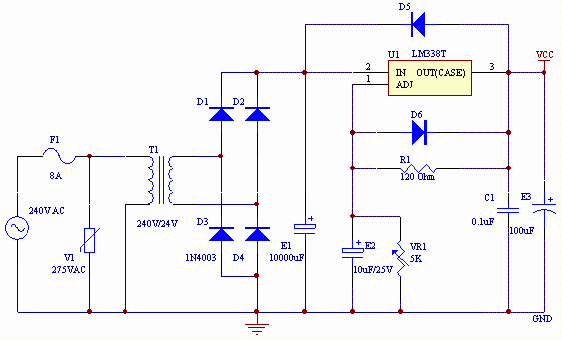
This project uses a LM338 adjustable 3 terminal regulator to supply a current of up to 5A over a variable output voltage of 2V to 25V DC. It will come in handy to power up many electronic circuits when you are assembling or building any electronic devices. The schematic and parts list are designed for a power supply input of 240VAC. Change the ratings of the components if 110VAC power supply input is required.


As shown in the figure above, the mains input is applied to the circuit through fuse F1. The fuse will blow if a current greater than 8A is applied to the system. Varistor V1 is used to clamp down any surge of voltage from the mains to protect the components from breakdown. Transformer T1 is used to step down the incoming voltage to 24V AC where it is rectified by the four diodes D1, D2, D3 and D4. Electrolytic capacitor E1 is used to smoothen the ripple of the rectified DC voltage.

Diodes D5 and D6 are used as a protection devices to prevent capacitors E2 and E3 from discharging through low current points into the regulator. Capacitor C1 is used to bypass high frequency component from the circuit. Ensure that a large heat sinkis mounted to LM338 to transfer the heat generated to the atmosphere.

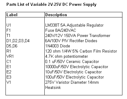
Parts List


http://www.electronics-project-design.com/PowerSupplySchematic.html

Saturday, October 16, 2010

DC Voltage Regulator dual Power Supply +5V to +25V, -5V to -25V 1A with LM7805 LM7905


When you want Dual power supply Variable Regulator be simple. I begs for to advise this circuit, because use the integrated circuit LM7805 and LM7905. Make have Voltage +5V to +25V and -5V to -25V unless. Still pay current get about 1A enough with general usability.


DC Voltage Regulator dual Power Supply +5V to +25V, -5V to -25V 1A with LM7805 LM7905
The important factor is you should use Transformer at enough size doesn’t lower 2A and IC all stick let off the heat with. The detail is other see in circuit picture better sir.

http://www.circuitpowersupply.com/circuitblog/dc-voltage-regulator-dual-power-supply-5v-to-25v-5v-to-25v-1a-with-lm7805-lm7905/

High Current Regulated Supply By LM317 and 2N3055×2


The high current regulator below uses an additional winding or a separate transformer to supply power for the LM317 regulator so that the pass transistors can operate closer to saturation and improve efficiency. For good efficiency the voltage at the collectors of the two parallel 2N3055 pass transistors should be close to the output voltage.
High Current Regulated Supply By LM317 and 2N3055×2
The LM317 requires a couple extra volts on the input side, plus the emitter/base drop of the 3055s, plus whatever is lost across the (0.1 ohm) equalizing resistors (1volt at 10 amps), so a separate transformer and rectifier/filter circuit is used that is a few volts higher than the output voltage. The LM317 will provide over 1 amp of current to drive the bases of the pass transistors and assumming a gain of 10 the combination should deliver 15 amps or more.
By Bill Bowden
Source :: http://ourworld.compuserve.com/homepages/Bill_Bowden/page12.htm

Simple DC voltage regulated 0-30V 3A


If you are looking for DC Voltage Reulator be simple. That can give Current tall about 3A and fine voltage get from 0-30V. As a result please consider this circuit before, it is easy. Because of have no the integrated circuit. Use the transistor is a principle especially the number MJ3001.


Simple DC voltage regulated 0-30V 3A
Usability just fine VR1 for control Volt output and choose the value Current get with S1. The detail is other see in the circuit help understand go up sir.

http://www.circuitpowersupply.com/circuitblog/simple-dc-voltage-regulated-0-30v-3a/

Variable Regulater Switching LAB Supply 50V 5A by TL494


Somsak is person see the website of me take an interest try build Variable Regulater Switching LAB Supply. By fine decorate voltage output get 0-50V and fine current get 5A. I then choose this circuit , which use IC TL494 be pillar equipment (Switchmode Pulse Width Modulation Control Circuit).


Variable Regulater Switching LAB Supply 50V 5A by TL494
And use pretty litter transistor number MJ15004 then give current get enough tall. But should choose pot size modifies about 5A go up with. When see the circuit has already may inappropriate with a novice. Because use many equipments then the gift uses the tie perhaps specially with , be lucky sir.
 
http://www.circuitpowersupply.com/circuitblog/variable-regulater-switching-lab-supply-50v-5a-by-tl494/

2N3055 variable supply 0-25V


One your friend beg for model the circuit about variable supply range 0-25V. I tries to search see meet voltage regulators circuits. The this be the circuit that use the transistor 2N3055 numbers are important equipment. Which be the equipment that seek good easy. fine P1 control current output the topmost.And fine P2 control Voltage range 0-25V.


2N3055 variable supply 0-25V
The detail is other invite read in original website http://www.redcircuits.com//Page36.htm

L200 DC Variable power 3-15volt at 2Amp


For the work experiences general that want power supply LAB. I thinks L200 DC Variable power Circuit. May like you , because of give Volt range about 3V-15V and Current 2A normal. When , you see the circuit. May search eyes and the integrated circuit that use be number L200 although old already.


L200 DC Variable power 3-15volt at 2Amp
But still be usable well the interesting. This important circuit that should use Transformer that be appropriate be 12V sizes and should use 2A more than because get current that straight follow want certainly give testimony grandmother horn forget to stick let off the heat gives with, IC L200 with appropriately. The detail is other see in the circuit and from original website
 
http://www.mitedu.freeserve.co.uk/Circuits/Power/l200var.html

10A Variable Regulator power supply with LM350


This be Variable Regulator power supply Circuit. That be High Current Source 10amp. By use the integrated circuit LM350. Which usual it controls Voltage output get 1.2V to 25V and give current about 3Amp.

But when bring parallel 3 pcs. Can give current output be 10Amp max for this circuit. It can adjustable voltage output get 4.5V to 25V at 10Amp. Other detail please see in the website Link.

3-30V 2.5A Stabilized power supply


This is a very useful project for anyone working in electronics. It is a versatile power supply that will solve most of the supply problems arising in the everyday work of any electronics work shop. It covers a wide range of voltages being continuously variable from 30 V down to 3 V.

The output current is 2.5 A maximum, more than enough for most applications. The circuit is completely stabilised even at the extremes of its output range and is fully protected against short-circuits and overloading.
Link

24V Variable DC Power Supply


A Variable DC Power Supply is one of the most useful tools on the electronics hobbyist’s workbench. This circuit is not an absolute novelty, but it is simple, reliable, “rugged” and short-proof, featuring variable voltage up to 24V and variable current limiting up to 2A.


Well suited to supply the circuits shown in this website. You can adapt it to your own requirements as explained in the notes below.
Link :

DC Power supply adjust voltage regulator 1.5 Volt - 15Volt 3Amp


I wants DC Power supply adjust voltage regulator 1.5 Volt - 15Volt, and give current about 3 Amp for in the work experiences all electronics. As seek many the circuit , meet that this circuit easily , use integrated number circuit LM1084 for control voltage model regulator adjustable voltage 1.5V - 15V. With fining decorates VR1. And should feedInput AC 18V 3A low like besides should hold let off the heat gives the integrated circuit LM1084 with. For the detail , see in the circuit.


http://www.circuitpowersupply.com/circuitblog/dc-power-supply-adjust-voltage-regulator-15-volt-15volt-3amp/

dc power supply adjustable voltage 0-30 Volt at 2 Amp


When you want DC power supply Circuit , model to fine the value Voltage get 0-30V for apply general work. I thinks this circuit may is appropriate , because of give current get 2 Amp enough be usable experience all get comfortablely. By it uses ordinary equipment seek easy be IC LM723 for control voltage the level is all and systematically protect completely. And still have 2N3055 number transistors help boost current give tall fair the work.


The detail is other , you have can to see in original website http://www.next.gr

Adjustable power supply 0.1V – 50V By CA3130 and 2N3055


This power supply circuit is highly stabilized that its output voltage will drop only 0.005% even though the load changes from 0 to 100%. Another excellent capability is that the output voltage will change only by 0.01% if the input voltage fluctuates. The capability if the circuit to be adjusted from 0.1V up to 50V is due to the application of opamp IC CA3130 in the circuit. Transistor T4 raises the output voltage to higher level, and at the same time it separates the lower level opamp from the high level of the output voltage. The reference voltage is supplied by IC1. It is a temperature compensated transistor array with 5 transistors. Four of these transistors are used as reference diodes and the fifth one sets the output impedance of the reference source.


The reference voltage is set through P1. The opamp CA3130 compares the reference voltage at its minus input to the output voltage at its input. The output voltage passes first through a voltage divider before it is fed into the plus input of the opamp. Transistors T1 and T2 work as darlington pair and amplifies the current. Transistor T3 functions as current limiter. The current limit is ajustable through P1, and the lowest current limit is 0.6 ampere. Once potentiometer P1 is set at maximum, current limiting is disabled.
Source: http://apowersupply.com/adjustable-power-supply-01v-50volts-3.html

2-25V DC Power Supply Schematic by LM338


This DC power supply circuit uses a LM338 adjustable 3 terminal regulator to supply a current of up to 5A over a variable output voltage of 2V to 25V DC. It will come in handy to power up many electronic circuits when you are assembling or building any electronic devices. The schematic and parts list are designed for a power supply input of 240VAC. Change the ratings of the components if 110VAC power supply input is required.


As shown in the figure above, the mains input is applied to the circuit through fuse F1. The fuse will blow if a current greater than 8A is applied to the system. Varistor V1 is used to clamp down any surge of voltage from the mains to protect the components from breakdown. Transformer T1 is used to step down the incoming voltage to 24V AC where it is rectified by the four diodes D1, D2, D3 and D4. Electrolytic capacitor E1 is used to smoothen the ripple of the rectified DC voltage.
http://www.circuitpowersupply.com/circuitblog/2-25v-dc-power-supply-schematic-by-lm338/

Negative Adjustable Power Supply Module by LM337


This power supply circuit module is a compact, easy to build. It uses negative variable power supply module. This power module is ideal for powering any application requiring a DC supply at current levels up to 1.5A.Diodes D1-4 form a bridge rectifier which converts the AC input voltage into a DC level. They also allow a DC input voltage to be connected either way around. Capacitor C1 smooths the DC output of the bridge whilst C2 provides high frequency decoupling. The LM337T is an adjustable regulator IC providing the desired output
voltage.


Diode D5 is reversed biased during normal operation and is used to protect the regulator if the output is connected to a voltage of the same polarity (eg battery). Diode D6 protects the regulator if a reverse polarity voltage is connected to the output.
Source:http://powersupplycircuit.blogspot.com
http://powersupplycircuit.blogspot.com/2009/02/negative-adjustable-power-supply-module.html

Mini Bench Power Supply by LM324-BUZ22


The power supply described here is a simple unit, easily constructed from standard components. It is only suitable for small loads but otherwise has all the characteristics of its bigger brethren. Between 18 V and 24 V is applied to the input, for example from a laptop power supply. This avoids the need for an expensive transformer and accompanying smoothing. No negative supply is needed, but the output voltage is nevertheless adjustable down to 0 V.


A difficulty in the design of power supplies with current limiting is the shunt resistor needed to measure the output current, normally connected to a differential amplifier. Frequently in simple designs the amplifier is not powered from a regulated supply, which can lead to an unstable current regulation loop. This circuit avoids the difficulty by using a low-cost fixed voltage regulator to supply the feedback circuit with a stable voltage. This arrangement greatly simplifies current measurement and regulation.
To generate this intermediate supply voltage we use an LM7815. Its output passes through R17, which measures the output current, to MOSFET T1 which is driven by the voltage regulation opamp IC1C. Here R11 and C4 determine the bandwidth of the control loop, preventing oscillation at high frequencies. R15 ensures that capacitive loads with low effective resistance do not make the control loop unstable. The negative feedback of AC components of thecurrent via R12 and C5 makes the circuit reliable even with a large capacitor at its output, and negative feedback of the DC component is via the low-pass filter formed by R14 and C6. This ensures that the voltage drop across R15 is correctly compensated for. C7 at the output provides a low impedance source for high-frequency loads, and R16 provides for the discharge of C17 when the set voltage is reduced with no load attached.


Source: http://powersupplycircuit.blogspot.com/

Stabilized Power Supply With Short Circuit Protection


Here is stabilised power supply with short circuit protection. It’s an efficient 4-stage stabilized power supply unit for testing electronic circuits; and it provides well regulated and stabilized output, which is essential for most electronic circuits to give proper results. The circuit provides an audio- visual indication if there is a short circuit in the PCB under test, so the power supply to the circuit ‘under test’ can be cut-off immediately to save the valuable components from damage.


The circuit provides four different regulated supply outputs (12V, 9V, 6V and 5V) and an unregulated 18V output, which are selectable through rotary switch S2. The selected output is indicated on the analogue voltmeter connected to the outputs rails.


Source: Authorized by D. Mohan Kumar, ELECTRONICS FOR YOU, July 2004

Low Dropout Adjustable Regulator by LM2941


We frequently acquire requests for voltage regulators for systems for which the accepted LM317 is not suitable. Although the LM317 can acquire ascribe voltages up to 3-40 Volts, and achievement adapted voltages from 1.2-37 Volts, it can alone achievement a reliable anchored voltage if the ascribe voltage is at atomic 2-3 Volts college than the called achievement voltage - e.g. to get a reliable 12.0V output, the ascribe voltage would charge to be 15V+. This voltage aberration is the dropout, the bulk of voltage alone (dissipated/wasted as heat) in the regulator.

Low Dropout Anchored Voltage Regulators
Where a anchored voltage regulator is required, article like the LM2940 ambit can be used. These are low dropout voltage regulators about accessible with anchored achievement voltages of 5, 10, 12, and 15 Volts.
Such a regulator is complete for use for archetype area 12V rated LED spotlights are to be powered with a 12V battery. The array voltage can ambit from 12.5 to 14+ Volts, and we charge a anchored 12.0V to ability the LEDs, so although an LM317 would not be reliable, the LM2940 (which will bead no added than 0.5 Volts) would accord a anchored 12.0V achievement beyond the abounding voltage ambit of the array reliably.
Unfortunatately we cannot use an LM2940 area a non-standard voltage - e.g. 8.50 Volts - is required. Ideally we appetite article with the adaptability of the LM317, but the low dropout characteristics of the LM2950. Fortunately such a basic exists and it is the LM2941 adjustable low bead out voltage regulator (which is pictured above).
The LM2941 can achievement voltages from 5.0 to 15.0 Volts * with a archetypal dropout voltage of aloof 0.5 Volts (@ 1 Amp, beneath for lower currents), and an complete best dropout of 1.0 Volts beyond the abounding temperature range. The LM2941 can accumulation up to 1 Amp of current.
* Note that the best ascribe voltage is 26 Volts, so this basic is not acceptable for 24 Volt rated systems.
Pictured aloft is the archetypal appliance ambit application the LM2941 as an adjustable voltage regulator. The advertence voltage (measured beyond ADJ and GND) is 1.275V. With the resistor R1 about set to 1K, the amount of R2 for any accustomed adapted achievement voltage is affected application the afterward equation:
R2 = R1 (( Vout / Vref) - 1 ))
For example, if an 8.00V low voltage bead out regulator is required, R1 = 1K, Vref = 1.275, and so R2 = 1000((8.00/1.275) - 1) = 5276 Ohms.
Turning the blueprint about we can additionally account the achievement voltage for any accustomed ethics of R1 and R2:
Vout = Vref * ((R1 + R2) / R1)
…so if we accumulate R1 as 1K and set R1 as 5K1 (since the 5276 Ohm amount affected is acutely not a accepted resistor) we see that Vout = 1.275 ((1000 + 5100) / 1000) = 7.78 Volts. (Note that it is accessible to affix accepted resistors in alternation abacus up their ethics to get an exact amount if a actual authentic voltage regulator is appropriate - e.g. 4K7 + 560R + 10R + 5R6 = 5276 Ohms for an 8.00V regulator)

High Current Regulated Supply By LM317 and 2N3055×2


transformer to supply power for the LM317 regulator so that the pass transistors can operate closer to saturation and improve efficiency. For good efficiency the voltage at the collectors of the two parallel 2N3055 pass transistors should be close to the output voltage.
High Current Regulated Supply By LM317 and 2N3055×2
The LM317 requires a couple extra volts on the input side, plus the emitter/base drop of the 3055s, plus whatever is lost across the (0.1 ohm) equalizing resistors (1volt at 10 amps), so a separate transformer and rectifier/filter circuit is used that is a few volts higher than the output voltage. The LM317 will provide over 1 amp of current to drive the bases of the pass transistors and assumming a gain of 10 the combination should deliver 15 amps or more.
 
By Bill Bowden
Source :: http://ourworld.compuserve.com/homepages/Bill_Bowden/page12.htm

5V 5A Higher currents by LM340-5 and 2N4398


If you want circuit to use a higher current regulator - up to 5A regulators are available. Please see here circuit,it good idea very much. In this circuit, the transistor Q1 is used to share some of the current supplied. The voltage regulator maintains the output voltage, and still operates short circuit protection.


5V 5A Higher currents  by LM340-5 and 2N4398
The current that the transistor takes is set by the resistor values R1 and R2, and is I = R2/R1 * RegulatorCurrent. The example shown converts a 1A regulator into a 5A (4A for the transistor plus 1A for the regulator) voltage regulator circuit. See the LM340 datasheet for a full description of this circuit.


http://www.circuitpowersupply.com/circuitblog/5v-5a-higher-currents-by-lm340-5-and-2n4398/

Power Supply Regulator Variable 3 - 24 Volt 3 Amp By LM1458 and 2N3055


This regulated power supply can be adjusted from 3 to 25 volts and is current limited to 2 amps as shown, but may be increased to 3 amps or more by selecting a smaller current sense resistor (0.3 ohm). The 2N3055 and 2N3053 transistors should be mounted on suitable heat sinks and the current sense resistor should be rated at 3 watts or more.

Power Supply Regulator Variable 3 - 24 Volt  3 Amp By LM1458 and 2N3055

Voltage regulation is controlled by 1/2 of a 1558 or 1458 op-amp. The 1458 may be substituted in the circuit below, but it is recommended the supply voltage to pin 8 be limited to 30 VDC, which can be accomplished by adding a 6.2 volt zener or 5.1 K resistor in series with pin 8. The maximum DC supply voltage for the 1458 and 1558 is 36 and 44 respectively. The power transformer should be capable of the desired current while maintaining an input voltage at least 4 volts higher than the desired output, but not exceeding the maximum supply voltage of the op-amp under minimal load conditions. The power transformer shown is a center tapped 25.2 volt AC / 2 amp unit that will provide regulated outputs of 24 volts at 0.7 amps, 15 volts at 2 amps, or 6 volts at 3 amps. The 3 amp output is obtained using the center tap of the transformer with the switch in the 18 volt position. All components should be available at Radio Shack with the exception of the
 
http://ourworld.compuserve.com/homepages/Bill_Bowden/

Easy DC Converter 12V to 24V


A friend of me wants the circuit enhances Voltage 12VDC from be 24VDC or DC to DC Converter 12V to 24V. By fix reveal that be the circuit is simple , build not difficult. I then advise this circuit try out think use just Transistors D1616 = 2 pcs. with transformer the small-sized , mix with other equipment a little only again. Follow a picture has can to use this circuit with small fan motor.
Easy DC Converter 12V to 24V


http://www.circuitpowersupply.com/circuitblog/easy-dc-converter-12v-to-24v/

Basic Step up voltage DC to DC converter by 74C14


When you want to experience build Step up voltage DC to DC converter. I thinks this circuit basically the base certainly. By use 74C14 integrated digital number circuits are pillar equipment. In the principle at the beginning can modify 1.5V DC electricity pressures have to 6V DC. With the techinque LC booster up voltage. For other detail , see in the circuit and original website
 
Basic Step up voltage DC to DC converter by 74C14

 
http://www.rowan.sensation.net.au/electronics/stepup.html better sir.

Power Filter Regulated for car by LM1084


When you lead to play MP3 or laptop computer come to apply to an automobile. Sometimes may born noise problem has from electricity automobile system. I thinks Power Filter Regulated for car by LM1084-12 may help solve a problem this get.

Power Filter Regulated for car  by LM1084

Because of using way LC filter and IC LM1084-12 (5A Low Dropout Positive Regulators) as a result can help regulate voltage well. If there is exceed noise 12V more although a little just will change this circuit has a little. And this circuit still can give the trend tall arrives at 5A can apply to the equipment cover very. The detail is other see from circuit picture and original website


http://linuxcar.sone.jp/reg.en.html

3V to 5V Dc converter by LT1073


If you have a place turns on the power 3V sizes, but want DC Voltage Regulator how are 5V. We sizes will make good. I has the exit, as a result build 3V to 5V Dc converter circuit. Which be not story difficult anything. if you use IC LT1073 of http://www.linear.com can count that be IC that good. You are supposed to keep to use very much. For Current output. as a result be valuable about 100mA enough be usable general get. When see the equipment adds that use. The a little there is important equipment be Diode D1 number 1N5818 and L1 = 68μH value. This circuit then for digital circuit. The small-sized request have fun it.
3V to 5V Dc converter by LT1073


http://www.circuitpowersupply.com/circuitblog/3v-to-5v-dc-converter-by-lt1073/

12V to 28V DC Converter By LM2585


Will do ? good! The exit is good. Be build DC to DC converter be 12VDC to 28VDC converter. By I uses the integrated circuit number LM2585 be pillar equipment for this work. Not difficult tell a lot of invite you see in circuit picture better.
12V to 28V DC Converter By LM2585


http://www.circuitpowersupply.com/circuitblog/12v-to-28v-dc-converter-by-lm2585/

1.5V to 5V DC Converter using LT1073


This is DC to DC Converter circuit. , It will change from DC Volt 1.5V boost up to 5V DC. It convenients for to are usable with digital circuit that use low current 100mA only. When see the detail in the circuit ,It the integrated circuit number LT1073 be main part. Then the circuit that build easy , good cheap. If you take an interest to try build this circuit can read the detail enhances from


http://www.linear.com or Will buy integrated number this circuit comes to try build see all right.

DC Power supply adjust voltage regulator 1.5 Volt - 15Volt 3Amp


I wants DC Power supply adjust voltage regulator 1.5 Volt - 15Volt, and give current about 3 Amp for in the work experiences all electronics. As seek many the circuit , meet that this circuit easily , use integrated number circuit LM1084 for control voltage model regulator adjustable voltage 1.5V - 15V. With fining decorates VR1. And should feedInput AC 18V 3A low like besides should hold let off the heat gives the integrated circuit LM1084 with. For the detail , see in the circuit.


http://www.circuitpowersupply.com/circuitblog/dc-power-supply-adjust-voltage-regulator-15-volt-15volt-3amp/

DC Power supply adjust voltage regulator circuit 1.5 Volt - 15Volt 3Amp


I wants DC Power supply adjust voltage regulator 1.5 Volt - 15Volt, and give current about 3 Amp for in the work experiences all electronics. As seek many the circuit , meet that this circuit easily , use integrated number circuit LM1084 for control voltage model regulator adjustable voltage 1.5V - 15V.


With fining decorates VR1. And should feedInput AC 18V 3A low like besides should hold let off the heat gives the integrated circuit LM1084 with. For the detail , see in the circuit.

http://www.circuitpowersupply.com/variable-voltage-regulator/0-30vdc-variable-voltage-regulator-lab-supply/

10A Variable Regulator power supply with LM350


This entry was posted on Wednesday, October 1st, 2008 at 8:08 am and is filed under High Current supply, dc voltage variable. You can follow any responses to this entry through the RSS 2.0 feed. Responses are currently closed, but you can trackback from your own site.


This be Variable Regulator power supply Circuit. That be High Current Source 10amp. By use the integrated circuit LM350. Which usual it controls Voltage output get 1.2V to 25V and give current about 3Amp. But when bring parallel 3 pcs. Can give current output be 10Amp max for this circuit. It can adjustable voltage output get 4.5V to 25V at 10Amp. Other detail please see in the website Link.


http://www.circuitpowersupply.com/circuitblog/10a-variable-regulator-power-supply-with-lm350/

dc-power-supply-6v-using-lm317


It uses integrated number circuit LM317T be important equipment. It can have the trend comes out about 1A by is character circuit DC voltage regulated. And have the circuit protects good. We can fix output voltage get from R1,R2. The diode D3-D4 (1N4002) use protect voltage flow turn back be bad with IC get. The Capacitors in the circuit helps Filter voltage smoothly and completed most. The transformer should choose 1A -2A size for current well sir.


http://www.circuitpowersupply.com/circuitblog/dc-power-supply-6v-using-lm317/

Friday, October 15, 2010

Voltage Variable Power Supply 0-12V 0.7A max 2A


This entry was posted on Friday, July 11th, 2008 at 8:10 am and is filed under dc voltage regulator, dc voltage variable, power supply. You can follow any responses to this entry through the RSS 2.0 feed. Responses are currently closed, but you can trackback from your own site. In the experiment builds power supply regulator the that.

I will begin with the circuit is simple before. Which in this circuit use a little equipment. Have just zener diode perform regulator and the transistor number BD679 perform enlarge the current tallly go up. For VR1 - 5K values perform to fine the voltage of output. By initial from 0V go to topmost about 12V and pay the Current has usual about 0.7A topmost about 2A depend on transformer with.The detail is other see take get from circuit picture follow Link the this


http://www.talkingelectronics.com/te_interactive_index.html

High Current and Variable Voltage Regulator supply 0-25V at 25A


This entry was posted on Wednesday, October 8th, 2008 at 9:33 am and is filed under High Current supply, power supply. You can follow any responses to this entry through the RSS 2.0 feed. Responses are currently closed, but you can trackback from your own site.

You who like to build project power supply, May ever use the integrated circuit LM723 It can work in the circuit, there is integrated this circuit with can change voltage output get 0-25V with VR1 And control current get moderately tall about 25A by fine at VR2. For transistor at do infront enlarge the trend tallly go up. Arrive at 25A that ,he chooses to use 2N6776 numbers s have been canning wasp parallel then enhance to enlarge the trend tall very , and may more than 2N3055 numbers with. For other detail , see in original website better
 
 
http://www.seits.org/features/pwrsup.htm

10,000x With One Transistor


For a collector follower with emitter resistor, you’ll often find that the gain per stage is no more than 10 to 50 times. The gain increases when the emitter resistor is omitted. Unfortunately, the distortion also increases. With a ubiquitous transistor such as the BC547B, the gain of the transistor is roughly equal to 40 times the collector current (Ic), provided the collector current is less than a few milliamps. Circuit diagram:

transistor booster circuit schematic

This value is in theory equal to the expression q/KT, where q is the charge of the electron, K is Boltzmann’s constant and T is the temperature in Kelvin.
For simplicity, and assuming room temperature, we round this value to 40. For a single stage amplifier circuit with grounded emitter it holds that the gain Uout /Uin (for AC voltage) is in theory equal to SRc. As we observed before, the slope S is about 40Ic. From this follows that the gain is approximately equal to 40I cRc. What does this mean? In the first instance this leads to a very practical rule of thumb: that gain of a grounded emitter circuit amounts to 40·I c·Rc, which is equal to 40 times the voltage across the collector resistor.If Ub is, for example, equal to 12 V and the collector is set to 5V, then we know, irrespective of the values of the resistors that the gain will be about 40R(12–5) = 280. Notable is the fact that in this way the gain can be very high in theory, by selecting a high power supply voltage. Such a voltage could be obtained from an isolating transformer from the mains. An isolating transformer can be made by connecting the secondaries of two transformers together, which results in a galvanically isolated mains voltage.That means, that with a mains voltage of 240 Veff there will be about 340 V DC after rectification and filtering. If in the amplifier circuit the power supply voltage is now 340 V and the collector voltage is 2 V, then the gain is in theory equal to 40 x (340–2). This is more than 13,500 times! However, there are a few drawbacks in practice. This is related to the output characteristic of the transistor. In practice, it turns out that the transistor does actually have an output resistor between collector and emitter.
This output resistance exists as a transistor parameter and is called ‘hoe’. In normal designs this parameter is of no consequence because it has no noticeable effect if the collector resistor is not large. When powering the amplifier from 340 V and setting the collector current to 1 mA, the collector resistor will have a value of 338 k. Whether the ‘hoe’-parameter has any influence depends in the type of transistor. We also note that with such high gains, the base-collector capacitance in particular will start to play a role.As a consequence the input frequency may not be too high. For a higher bandwidth we will have to use a transistor with small Cbc, such as a BF494 or perhaps even an SHF transistor such as a BFR91A. We will have to adjust the value of the base resistor to the new hfe. The author has carried out measurements with a BC547B at a power supply voltage of 30 V. A value of 2 V was chosen for the collector voltage. Measurements confirm the rule of thumb. The gain was more than 1,000 times and the effects of ‘hoe’ and the base-collector capacitance were not noticeable because of the now much smaller collector resistor.


http://www.extremecircuits.net/2010/05/10000x-with-one-transistor.html

Sunday, October 10, 2010

Sine Wave To TTL Converter

Sine_Wave_to__TTL_Converter_Circuit_Diagram

As the title implies, the present circuit is intended to convert sinusoidal input signals to TTL output signals. It can handle inputs of more than 100 mV and is suitable for use at frequencies up to about 80 MHz. Transistor T1, configured in a common-emitter circuit, is biased by voltage divider R3–R5 such that the potential across output resistor R1 is about half the supply voltage. When the circuit is driven by a signal whose amplitude is between 100 mV and TTL level (about 2 V r.m.s.), the circuit generates rectangular signals. The lowest frequencies that could be processed by the prototype were around 100 kHz at an input level of 100 mV, and about 10 kHz when the input signals were TTL level.Resistor R6 holds the input resistance at about 50 Ω, which is the normal value in measurement techniques. It ensures that the effects of long coaxial cables on the signal are negligible. If the converter is used in a circuit with ample limits, R6 may be omitted, whereupon the input resistance rises to 300 Ω.


http://www.extremecircuits.net/2010/06/sine-wave-to-ttl-converter.html

Diode Radio For Low Impedance Headphones

Diode_Radio_for_Low_Impedance_Headphonesw

you ever look at construction notes for building old detector type radios the type of headphones specified always have an impedance of 2 × 2000Ω. Nowadays the most commonly available headphones have an impedance of 2 × 32 Ω, this relatively low value makes them unsuitable for such a design. However, with a bit of crafty transformation these headphones can be used in just such a design. To adapt them, you will need a transformer taken from a mains adapter unit, the type that has a switchable output voltage (3/4.5/6/9/12 V) without the rectifying diodes and capacitor. Using the different taps of this type of transformer it is possible to optimize the impedance match.For the diode radio (any germanium diode is suitable in this design) the key to success is correct impedance matching so that none of the received signal energy is lost. The antenna coil on the 10 mm diameter by 100 mm long ferrite rod is made up of 60 turns with a tap point at every 10 turns; this is suitable for medium wave reception. If a long external aerial is used it should be connected to a lower tap point to reduce its damping effect on the circuit. You can experiment with all the available tapping points to find the best reception. With such a simple radio design, the external aerial will have a big influence on its performance.
Tip:
If your house has metal guttering and rain water pipes, it will be possible to use these as an aerial, as long as they are not directly connected to earth. Those who live in the vicinity of a broadcast transmitter may be able to connect a loudspeaker directly to the output or if the volume is too low, why not try connecting the active speaker system from your PC?


http://www.extremecircuits.net/2010/07/diode-radio-for-low-impedance.html

One Transistor Radio

 One_Transistor_Radio_Circuit_Diagramw                                                              Here is a simple circuit for a one transistor Audion type radio powered by a 1.5 V battery. It employs a set of standard low-impedance headphones with the headphone socket wired so that the two sides are connected in series thus giving an impedance of 64 Ω. The supply to the circuit also passes through the headphones so that unplugging the headphones turns off the supply. Using an Audion configuration means that the single transistor performs both demodulation and amplification of the signal.The sensitivity of this receiver is such that a 2 m length of wire is all that is needed as an antenna. The tap on the antenna coil is at 1/5th of the total winding on the ferrite rod. For details of the antenna coil see the article Diode Radio for Low Impedance Headphones. This circuit is suitable for reception of all AM


http://www.extremecircuits.net/2010/07/one-transistor-radio.html

Low Power FM Transmitter

p90-f1

This article should satisfy those who might want to build a low power FM transmitter. It is designed to use an input from another sound source (such as a guitar or microphone), and transmits on the commercial FM band - it is actually quite powerful, so make sure that you don't use it to transmit anything sensitive - it could easily be picked up from several hundred metres away. The FM band is 88 to 108MHz, and although it is getting fairly crowded nearly everywhere, you should still be able to find a blank spot on the dial.
NOTE: A few people have had trouble with this circuit. The biggest problem is not knowing if it is even oscillating, since the frequency is outside the range of most simple oscilloscopes. See Project 74 for a simple RF probe that will (or should) tell you that you have a useful signal at the antenna. If so, then you know it oscillates, and just have to find out at what frequency. This may require the use of an RF frequency counter if you just cannot locate the FM band.
Description
The circuit of the transmitter is shown in Figure 1, and as you can see it is quite simple. The first stage is the oscillator, and is tuned with the variable capacitor. Select an unused frequency, and carefully adjust C3 until the background noise stops (you have to disable the FM receiver's mute circuit to hear this).


http://www.extremecircuits.net/2010/08/low-power-fm-transmitter.html

Friday, October 8, 2010

DC/DC Converter From +1.5V To +34V

An interesting DC/DC converter IC is available from Linear Technology. The LT1615 step-up switching voltage regulator can generate an output voltage of up to +34V from a +1.2 to +15V supply, using only a few external components. The tiny 5-pin SOT23 package makes for very compact construction. This IC can for example be used to generate the high voltage needed for an LCD screen, the tuning voltage for a varicap diode and so on. The internal circuit diagram of the LT1615 is shown in Figure 1. It contains a monostable with a pulse time of 400 ns, which determines the off time of the transistor switch.If the voltage sampled at the feedback input drops below the reference threshold level of 1.23 V, the transistor switches on and the current in the coil starts to increase. This builds up energy in the magnetic field of the coil. When the current through the coil reaches 350 mA, the monostable is triggered and switches the transistor off for the following 400 ns. Since the energy stored in the coil must go somewhere, current continues to flow through the coil, but it decreases linearly. This current charges the output capacitor via the Schottky diode (SS24, 40V/2A). As long as the voltage at FB remains higher than 1.23V, nothing else happens.
As soon as it drops below this level, however, the whole cycle is repeated. The hysteresis at the FB input is 8mV. The output voltage can be calculated using the formula Vout = 1.23V (R1+R2) / R2 The value of R1 can be selected in the megohm range, since the current into the FB input is only a few tens of nano-amperes. When the supply voltage is switched on, or if the output is short-circuited, the IC enters the power-up mode. As long as the voltage at FB is less than 0.6V, the LT1615 output current is limited to 250mA instead of 350mA, and the monostable time is increased to 1.5µs.These measures reduce the power dissipation in the coil and diode while the output voltage is rising. In order to minimize the noise voltages produced when the coil is switched, the IC must be properly decoupled by capacitors at the input and output. The series resistance of these capacitors should be as low as possible, so that they can short noise voltages to earth. They should be located as close to the IC as possible, and connected directly to the earth plane. The area of the track at the switch output (SW) should be as small as possible. Connecting a 4.7-µF capacitor across the upper feedback capacitor helps to reduce the level of the output ripple voltage.

Switching Voltage Regulator


The Analog Devices ACP3610 is a voltage doubler that works with a switched-capacitor converter, using the push-pull principle. The switching frequency at the output is approximately 550 kHz. The term ‘push-pull’ refers to the two charge pumps, which work in parallel but in opposite directions in order to deliver the output voltage and current. Whenever one capacitor is supplying current to the output, the other one is being charged. This technique minimizes voltages losses and output ripple. The converter works with input voltages between 3 and 3.6 V. It provides an output voltage of around 6V at a maximum current of 320mA, if 2.2µF switched capacitors with low ESR (equivalent series resistance) are used.
A shut-down input is provided to allow the voltage doubler to be enabled or disabled by a logic-level signal. The IC is enclosed in a special package, which can dissipate up to 980mW at room temperature. The schematic diagram shows a typical application for the ADP3610. Here it works as a non-regulated voltage doubler. In theory, a voltage doubler can provide exactly twice the input voltage at its output, but in practice the combination of internal losses in the electronic switches and the internal resistances of the capacitors always causes the output voltage to be somewhat lower. The output voltage drops from a no-load value of 6 V to 5.4 V with a 320mA load, with a nearly linear characteristic.

A small capacitor is connected across the two supply pins at the input of the IC. It suppresses noise, brief voltage fluctuations, and current peaks when the ADP3610 switches. This capacitor (CIN) must have a low internal resistance (ESR). A larger capacitance value is necessary if long supply leads to the ADP3610 are present. The 1µF output capacitor (CO) is alternately charged by the two capacitors of the charge pump, CP1 and CP2. The internal resistance is an important factor here as well. It largely determines the amount that the voltage drops under load, and the amount of ripple in the output voltage. Ceramic or tantalum capacitors are recommended. The ESR can also be reduced by connecting several smaller-value capacitors in parallel. With small loads, the value of CO may be reduced.


http://www.extremecircuits.net/2010/08/switching-voltage-regulator.html

Thursday, October 7, 2010

Variable Voltage Regulator using the L200


This is a circuit diagram of the circuit variable regulator, which uses IC L200, as regulator of voltage and current, IC For this comes from the company SGS-Thomson, which gives this series. This diagram circuit output voltage can be set, we can set the output voltage, with RV1. You can use this power supply circuit in various applications


Component :
R1=0.7 / Io max
R2=10 ohms
R3=1Kohm
R4=820 ohms
RV1=4.7Kohm pot.
C1=4700uF 63V
C2-3=100nF 100V
C4=47uF 63V
Q1=BDW51
Q2=BC108
IC1=L200

Voltage Regulator Using LM338


This circuit is a circuit diagram power supply. Circuit diagram works on voltage +13.8 V 5A with electric currents. This circuit controlled by the LM338 IC. Many times we need a supply of relatively strong in the framework we provide a variety of equipment with + 13.8V, as transceivers CB, cargo lead-acid batteries, and others known to use the circuit capable of providing complete in his exit, when This continuously operating 5A and 12A peak current. Not only need a few external components. Setting the voltage at + 13.8V to the trimmer TR1, (multiturn). The IC1 LM338 must in each case is placed on one suitable heatsink, which both supported by one fan. All the connections by the circuit become with big cross-section cable, because the current through from within their already high enough. The following is a schematic drawing:
Component :
R1=270R 1/4W 2%
TR1=4k7 (Multiturn)
C1=10000uF 40V
C2-3=100 nF 100V Polyester
C4-5=10uF 25V
D1-2=1N4002 (1A/100V)
B1=25A Bridge Rectifier
IC1=LM338
T1=220Vac/15VAC – 8A Mains Transformer
S1=2 Pole Single Throw Mains Switch
F1=250mA Fuse

http://freecircuitdiagram.net/voltage-regulator-using-lm338.html

2-25V 5A Power Supply Using LM338


This circuit is a circuit diagram power supply circuit uses a LM338 adjustable 3 terminal regulator to supply a current of up to 5A over a variable output voltage of 2V to 25V DC. It will come in handy to power up many electronic circuits when you are assembling or building any electronic devices. The schematic and parts list are designed for a power supply input of 240VAC. Change the ratings of the components if 110V AC power supply input is required. The mains input is applied to the circuit through fuse F1. The fuse will blow if a current greater than 8A is applied to the system. Varistor V1 is used to clamp down any surge of voltage from the mains to protect the components from breakdown. Transformer T1 is used to step down the incoming voltage to 24V AC where it is rectified by the four diodes D1, D2, D3 and D4. Electrolytic capacitor E1 is used to smoothen the ripple of the rectified DC voltage.
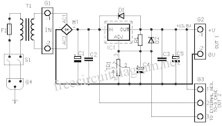
Diodes D5 and D6 are used as a protection devices to prevent capacitors E2 and E3 from discharging through low current points into the regulator. Capacitor C1 is used to bypass high frequency component from the circuit. Ensure that a large heat sink is mounted to LM338 to transfer the heat generated to the atmosphere.
2-25V Power Supply Parts List


http://freecircuitdiagram.net/2-25v-5a-power-supply-using-lm338.html